Surface-Based Modeling in CAD
At some point, CAD designers transition from solid modeling to surface-based modeling. This requires a greater understanding of modeling compared to the relatively intuitive way that solid modeling is performed. This will hopefully shed some light on common surface modeling terms and techniques. For this article, I used both CATIA and SolidWorks to generate the images shown.
Plane surfaces describe the infinite plane created by three non-coincident points. Planar surfaces are typically used to describe the origination point and relative geometry of sketches in certain CAD systems. Planar surfaces are the preferred method of creating relational designs due to the ease by which the offset amounts may be modified to change overall part geometry quickly. Planar surfaces are the default geometry found in most CAD programs and are typically available for editing in all workbenches as applicable.
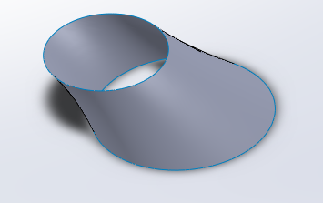
Lofted surfaces are planar surfaces created from curves. Lofted surfaces are typically used to generate solid geometry, such as pipes and airframe components on airplanes. SolidWorks automatically creates lofted surfaces but requires additional steps in the CATIA Generative Shape Design workbench. The Lofted Surface was made in the same way tubes normally are. I created a spline by assigning Geometrical Set points, created a profile shape, then created a surface that followed the spline using the profile shape.
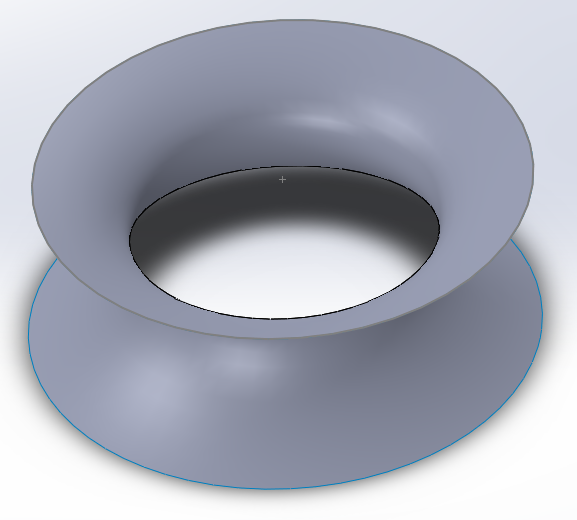
Ruled surfaces are a surface that is defined by boundary curves. It is linearly interpolated to achieve a filled result from lines drawn from the boundary curves. Conic or hyperbolic sections are examples of ruled surfaces. These must be created by hand in CATIA and SolidWorks.The Ruled Surface was created using offset planes with circular sketches joined with surfaces. All other CATIA intersections, divisions, and solid creations followed the same path.
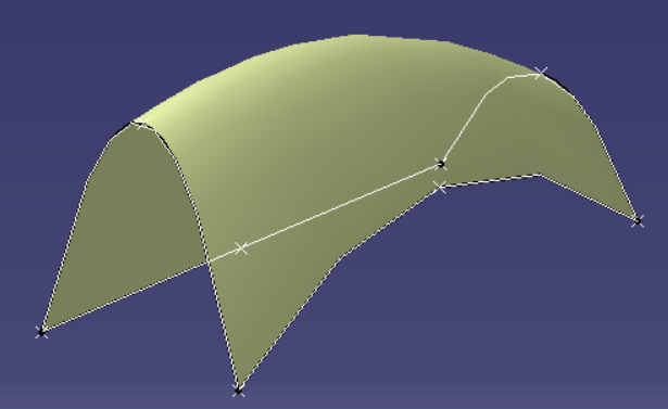
Coons surfaces are curve-bounded surfaces created by filling in an area between multiple curves. Coons surfaces are especially useful in patching surface geometry errors such as those created by inaccurate plane creation resulting in holes in the design. These must be created manually in most CAD programs; however, some newer animation software may accomplish creation automatically. The Coon's Patch was created by filling the space between four splines.
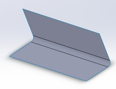
Fillet surfaces are B-splines that join two adjacent planar surfaces. Fillets are used in both surface and solid geometry to reduce manufacturing costs. Fillets are baseline CAD features and are available in both Solidworks and CATIA for both surface and solid geometry. These features may be directly added to perpendicular surfaces in most CAD programs. This surface fillet was created by manually creating surface profiles, then joining them directly and trimming the leftover material.
Offset surfaces allow for the creation of a duplicate surface that has the same relative dimensions; however, the dimensions are of a larger magnitude. Offset surfaces are especially useful for creating shell-like surface geometry. Offset surfaces may be created automatically in both CATIA and SolidWorks. Offset surfaces allow CAD designers to quickly and efficiently fill an area by thickening or joining surfaces.
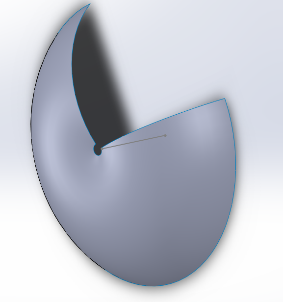
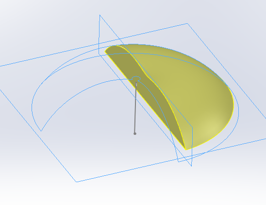
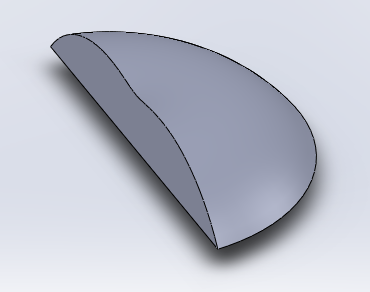
Revolved surfaces are planes, or sketches revolved about an axis by a certain angular displacement. The surface is interpolated between the starting and ending point to create a filled result. These may be created automatically in most CAD programs. The Solid of Revolution was created by revolving a surface sketch. The Offset Surface shown was then intersected, divided, and thickened to create uniquely shaped solid geometry.
By utilizing the different shapes shown in this article, you may find a few new ways to solve challenging CAD problems. As always, practice makes perfect!


Member discussion