Design for Manufacturing: Special Clearances
This article discusses cutter clearance in milling operations focusing on shoulders, flanges, and near the parting lines.
Cutter placement is sometimes neglected when placing features on machined parts. Without having a clear path for the cutter to reach the destination that requires subtractive manufacturing, the feature is not possible to create. Impossible geometry is a common problem for designers in the early stages of their careers.
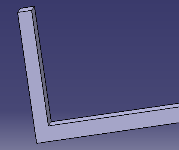
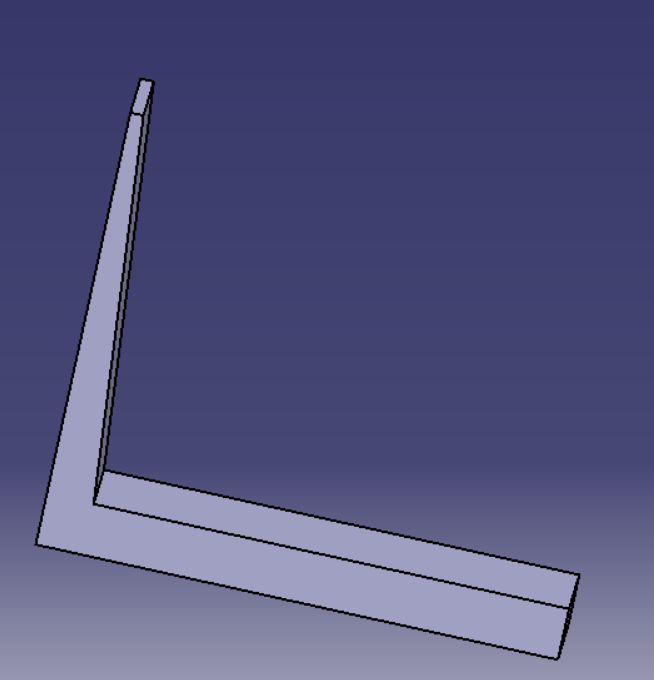
If a feature must be created immediately adjacent to a wall, it is unlikely that the cutter can be placed in such a location. Design engineers must take care that they space features far enough away from shoulders and flanges for the cutter to be able to reach. If the cutter cannot reach the destination, the part is impossible to create. As a result, the design engineer will have to redesign the part, which will add substantial time and cost.


Like ensuring that a tool path exists, design engineers must ensure that the tool path avoids areas of flash formation and parting lines. Areas where welds have been performed should also be avoided.
This is due to the chance of damaging the cutter. Areas with flash and parting lines may react unexpectedly to the forces imposed by a cutting blade. Weldments have undergone substantial material transition and may require a different type of cutter depending on the type of weld performed.
Key points:
If shoulders, flanges, or similar features are present or if parting lines or flash are present:
(a) Provide clearance for the cutter path.
(b) Consider the use of small radii cutters.
(c) Consider the use of stepped shoulders.
(d) Avoid cutting operations near weldments, parting lines, and flash.
The use of the items discussed in this article will allow for the machining of parts that otherwise may not be possible to machine. Additionally, cutter failure will occur less frequently, reducing tooling costs and manufacturing time due to fewer replacement cutters needing to be installed.


Member discussion