Design for Manufacturing: Gang Milling
This article looks at the time and tooling considerations behind gang milling.

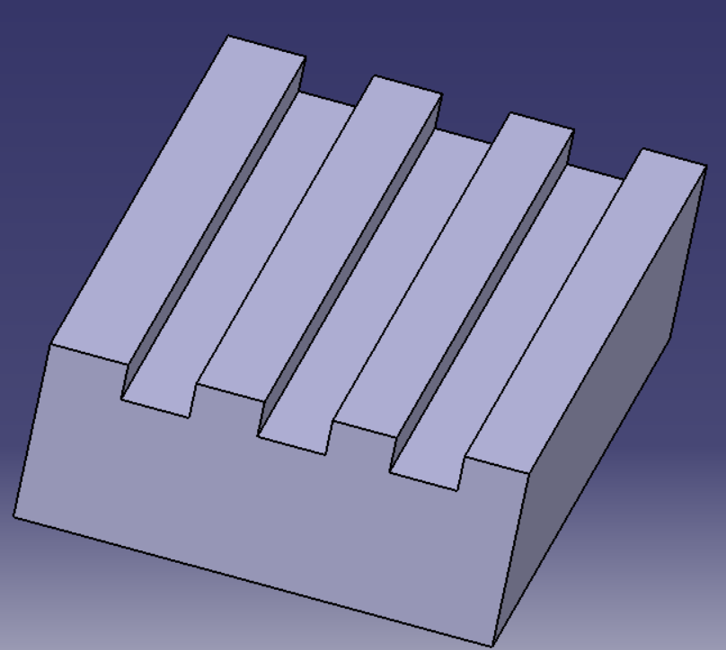
Gang milling is the process by which multiple part features are simultaneously created. This is accomplished using more than one cutter mounted on the same mandrel. This allows the same prime mover to drive all cutters simultaneously. If a part has repetitive features, these features may be produced simultaneously to reduce tooling setup and manufacturing flow times.
Before the invention of CNC machining, gang milling was critical in efficient product creation. Despite its replacement by CNC machining, gang milling is still used in situations where it is warranted. Design engineers are encouraged to use repetitive features when possible to allow gang milling to be applied to the workpiece.


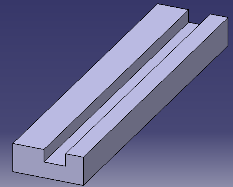
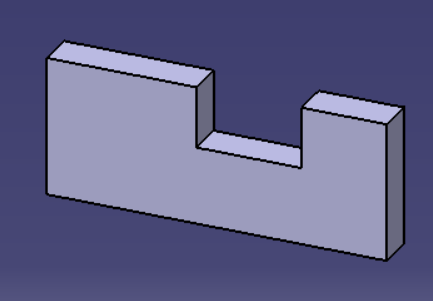
Similar to gang milling is the practice of cutting parts from a machined extrusion. In this situation, a long extrusion is worked by the milling machine. At the completion of the work, the workpiece is sliced into individual parts. This allows for bulk part creation with minimal tooling cost increase. The creation of parts in this way follows the same design constraints associated with gang milling.
Key points:
(a) When possible, attempt to design features of the same size and orientation
(b) Place features on the same plane
(c) These repetitive features should be gang-milled when possible to reduce processing time
(d) When possible, use single milling actions on a long extrusion, then slice the extrusion to make the individual parts
Use of what we covered in this article will reduce process costs from changing out tools. This will also substantially improve part manufacturing speed.


Member discussion